Egge Engine Tech

Correct Compression Ring Installation
Listed below are the general rules for the installation of various types of compression rings.
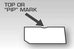
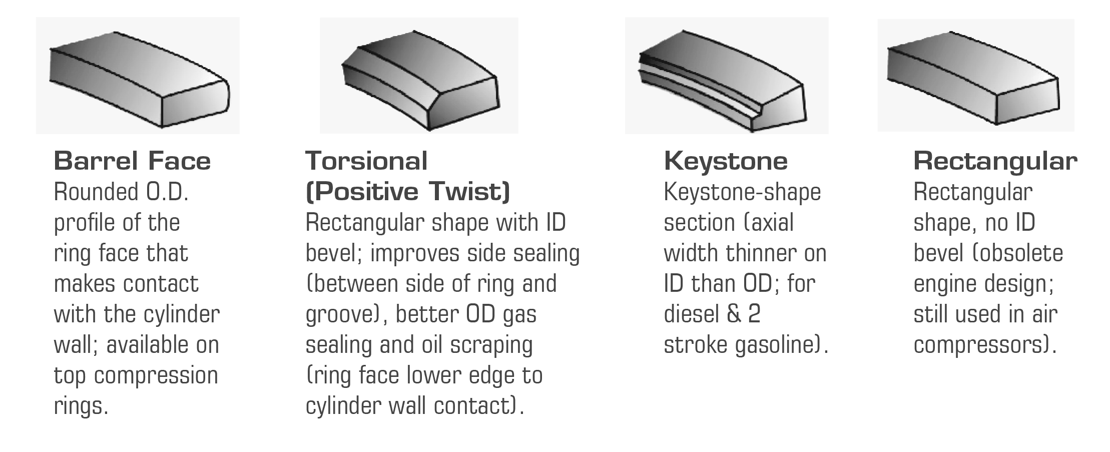
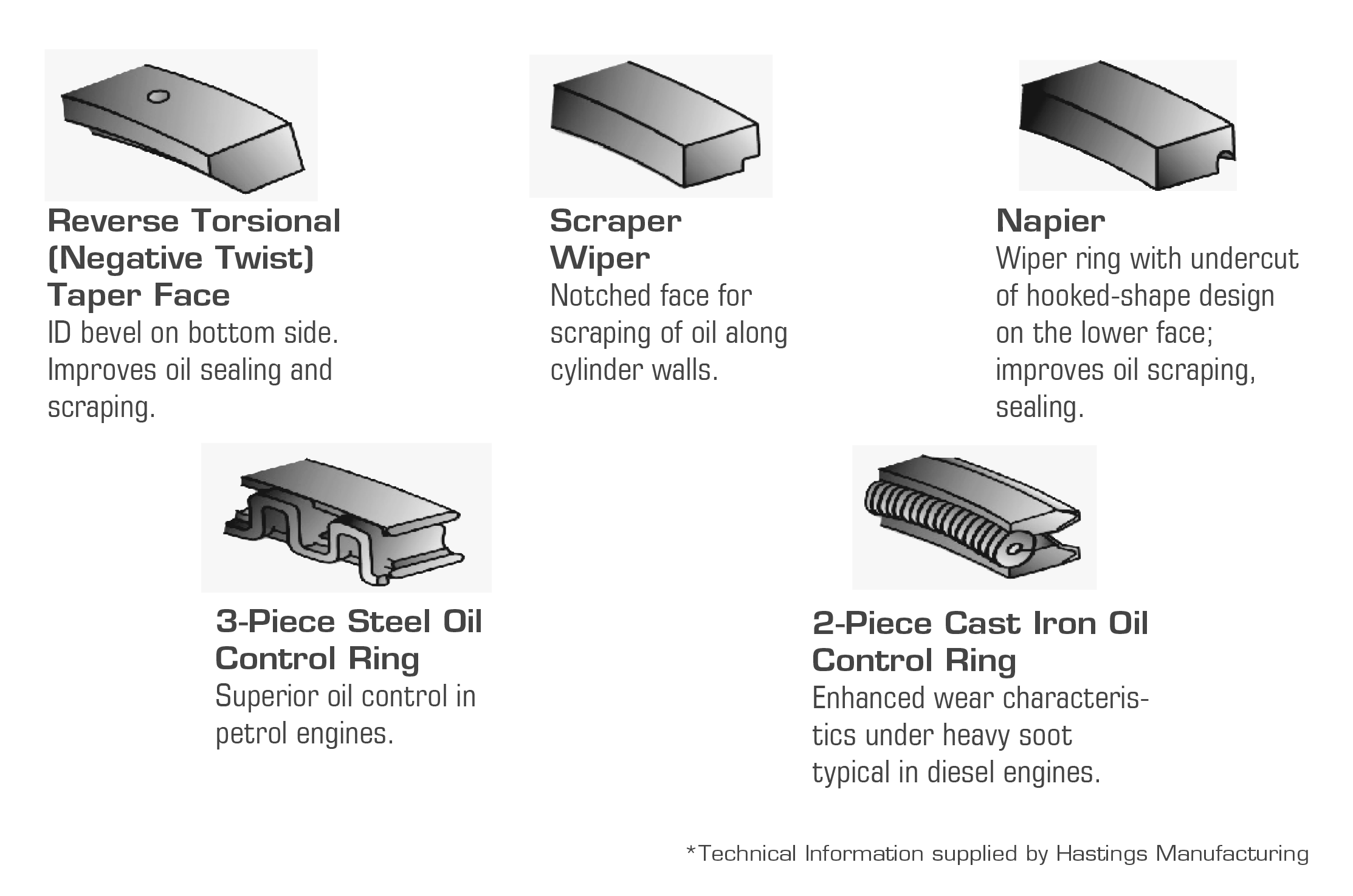
Rings having a "pip" mark or dot on the side of the ring must always be installed with the "pip" mark or dot towards the top of the piston.
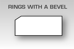
Rings with a bevel on the inside diameter but no "pip" mark or dot must be installed with the bevel towards the top of the piston.
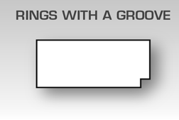
Rings with a groove or step in the outside diameter and no "pip" mark or dot must be installed with the groove toward the bottom of the piston.
It is a good idea after installing all rings on the pistons to recheck each ring on each piston for correct installation.
Rings having no dots, bevels, tapers, or grooves can be installed either way.
*Technical Information supplied by Hastings Manufacturing

Ring Installation
The event of engine downsizing has caused many changes in almost every engine component. Piston rings are no exception. They have been reduced in diameter as cylinder bores have become smaller, with corresponding width and wall reductions. Compression rings 1.5 mm wide (.0575") are becoming more common than rings which are 2.0mm (.0775") or wider.
This reduction in the cross sectional size of the ring has caused the ring to become somewhat more fragile with respect to handling than rings of larger cross sectional size. For this reason it is necessary to use care whenever these rings are being handled, but most importantly when the ring is being installed on the piston.
Care should be taken to follow the instructions below:
1. Use proper piston ring installation tools.
2. Keep the ring absolutely flat when opening to install on the piston.
3. Place the ring squarely in the groove and carefully release the tension of the ring installer.
If these procedures are not followed, damage will occur to the axial and/or radial shape of the ring, as illustrated below.
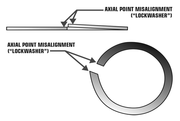
If the rings are installed after this type of damage has been inflicted, engine performance will be affected. Blow-by will increase and oil control will suffer.
Compression rings must never be spiraled on the piston.
Remember, these procedures are always important in all piston ring installations, and the more fragile the ring, the more care must be exercised.
*Technical Information supplied by Hastings Manufacturing

Piston Ring Installation Tips
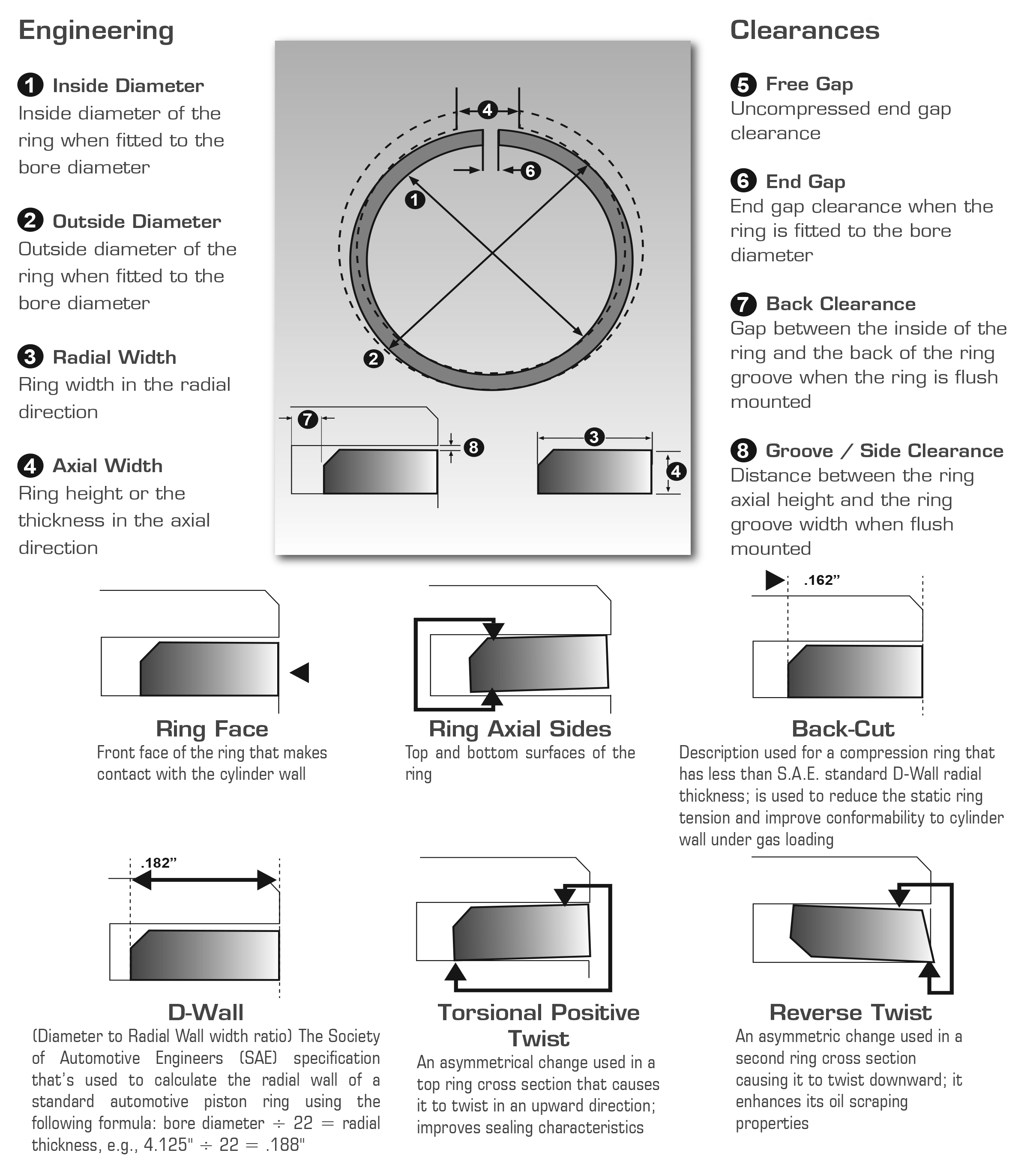
- Insert rings squarely into the bore before installing on piston. Measure end gap with feeler gauge.
- Adjust gap if needed by filing both sides of gap equally. (See Compression Ring Gap Clearances)
- Use ring expander tool to install rings on piston, so as not to deform ring—do not "spiral" on rings.
- Install directional rings with the dot up (otherwise oil pumping may occur).
- Install 3-piece oil ring with expander points up to avoid catching in drain-back hole/slot in oil groove bottom.
- Stagger location of end gaps on each ring 180 degrees apart.
- Clean bores with hot soapy water & scrub brush, wipe with clean white rag to check for any residue.
- Lightly oil cylinder walls and rings with regular non-synthetic motor oil.
- Properly tighten ring compressor so rings don't catch on edge of cylinder or pop out in bore (don't force piston if it is hung up).
- Typical engine break-in: use conventional motor oil with zinc additive or oil with zinc—change oil after first 3,000 miles. Use only synthetic motor oil if originally specified by manufacturer.
*Technical Information supplied by Hastings Manufacturing

Compression Ring Gap Clearances
| Ring Diameter | End Clearance Inspection Limit | ||
|---|---|---|---|
| 1.0000 | 2.3624 | 0.006 | 0.014 |
| 2.3625 | 2.9524 | 0.008 | 0.016 |
| 2.9525 | 3.5424 | 0.010 | 0.020 |
| 3.5425 | 4.3299 | 0.012 | 0.022 |
| 4.3300 | 5.1174 | 0.014 | 0.026 |
| 5.1175 | 5.9049 | 0.016 | 0.030 |
| 5.9050 | 6.8899 | 0.020 | 0.035 |
| 6.8900 | 8.9999 | 0.024 | 0.041 |
| 9.0000 | 10.9999 | 0.029 | 0.047 |
*Technical Information supplied by Hastings Manufacturing


Detonation and Pre-ignition Failure Analysis
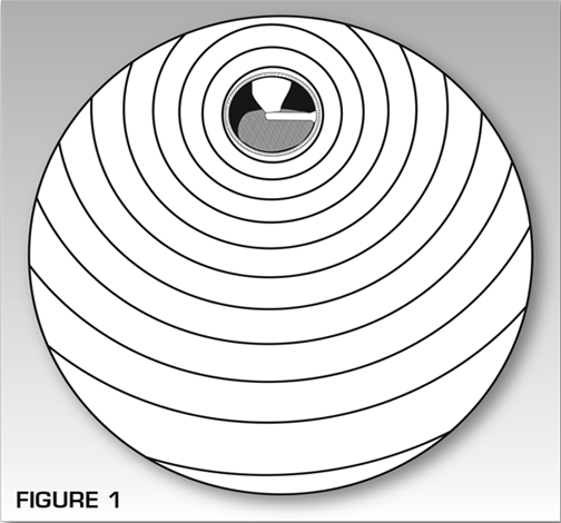
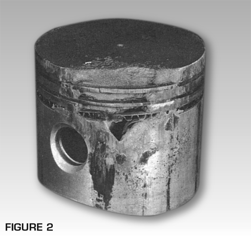
Abnormal operation may allow combustion pressures to develop so fast that the heat and pressure will "explode" the remaining unburned fuel. This produces the knock, often called "ping", carbon knock, etc.
Actually this is detonation. The knock results from the violent explosion when the normal flame front runs into the secondary flame front. Detonation will cause piston and ring damage, top ring groove wear, scoring, sticking rings, blown head gaskets and possible complete engine failure (see Fig. 2).
Detonation can be caused by:
- Lean fuel mixture
- Fuel octane too low
- Improper ignition timing
- Lugging of engine
- Carbon deposits
- Excessive milling of heads or block, which will increase compression ratio.
Pre-ignition, as the term suggests, is the ignition of the fuel-air mixture before the regular ignition spark from the spark plug. If the regular spark occurs shortly after the pre-ignition, the colliding of the two flame fronts will cause a pinging noise. Pre-ignition causes loss of engine power and can cause severe damage to pistons, rings and valves (See Fig. 3).
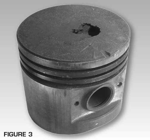
Detonation and pre-ignition are so closely related that it is often difficult to distinguish one from the other by sound. Each can lead to the other and either condition can cause extensive engine damage. Inspection of damaged pistons and rings quite often indicate which caused the damage.
Damaged pistons and rings usually mean replacement. The same damage can occur again unless the cause of the detonation or pre-ignition is corrected.
Pre-ignition can be caused by:
- Carbon deposits that remain incandescent.
- Spark plugs that are too hot of a heat range.
- Spark plugs not firmly seated against gasket.
- Detonation or the condition leading to it.
- Sharp edges in combustion chamber.
- Valves operating at higher than normal temperature because of excessive guide clearance or improper seal with valve seats.
- Overheating.
- Ignition crossfiring. Induced voltage in spark plug wires that run parallel to each other for long distances.
*Technical Information supplied by Hastings Manufacturing

Overheated Piston
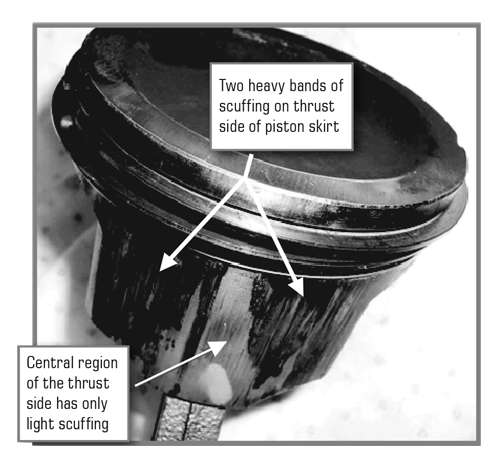
Image shows piston with oil caked below ring belt, again, indicating excessive cylinder temperature.
*Technical Information supplied by Hastings Manufacturing

Overheated Rings
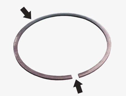
Image shows a ring which was removed from an overheated engine.
You'll notice the bluish cast, lack of free gap (loss of ring tension) and misalignment of ring points.
*Technical Information supplied by Hastings Manufacturing


